Additional information on use of the MSI software is available in Section AS-2 of the MSI reference manual.
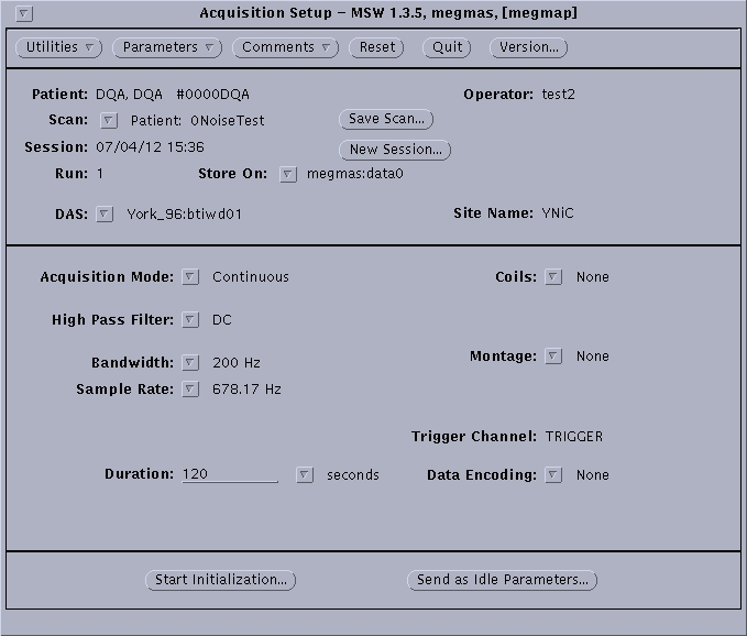
- On the “Patient Window”. Click on “Acquisition Setup”. The following window shown in Figure 6.2 will appear.
- Click on “Acquisition Mode” and select the appropriate option:
- “External” is used when the trigger is produced from an external program, e.g. Cambridge Research Systems.
- “Internal” is used when Megmap itself generates the trigger.
- “Continuous” is used when you want to record all data from a specified time interval (N.B. if this option is selected no epoch specification is required, ignore stages 4 and 5 and instead specify “Duration” of the experiment in seconds allowing extra time for unforeseen delays during the experimental procedure).
- Click on “Data Type” and specify which form of data you wish to collect:
- “Raw” collects only raw data. It is advised to select “Raw” because you can average the data at a later point.
- “Raw and Average” collects raw data as well as calculating an online average.
- “Average” calculates only an average of the data and does not store raw data (N.B. this option is rarely required).
- Enter values for “Epoch Duration”, “Pretrigger Duration” and “Number of Epochs” as determined by your experimental design. (N.B. Epoch Duration should be calculated to include the Pretrigger Duration).
- Click on “High Pass Filter” and select the appropriate value from the drop-down menu. The default and recommended filter is DC, as this preserves all the data. Some experiments may wish to acquire data with a 1 Hz filter, if they have a good reason to. However, we do not recommend recording with a 0.1 Hz filter.
- Click on “Bandwidth” and select appropriate value (usually 200 Hz) from the drop-down menu. The bandwidth is set at 200 Hz because users are not usually interested in acquiring data at frequencies higher than 200 Hz.
- Check that “Sample Rate” is set to 678.17Hz. The default sample rate is set at 678.17Hz because most users are interested in responses below 40 Hz. Additionally, using a higher sample rate requires a larger amount of disc storage.
- Click on “Coils” and select “5 coils” from the drop-down menu.
- Click on “Coil Acquisition Prompt” and select appropriate option from the drop-down menu:
- “Prompt” provides a prompt warning window before head coil positions are acquired before and after the experiment.
- “Don't Prompt” does not provide a prompt window before acquiring head coil positions before and after the experiment.
- Click on “Transform Calculation” and select “Coil Matching” from the drop-down menu.
- Click on “Montage” and select “5 Coils” from the drop down menu.
- Do not change settings for “Trigger Channel” or “Data Encoding”.
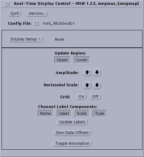
- Click on “Parameters” and select “Real Time Display” from the drop down menu. The window shown in Figure 6.3 will appear.
- Select a display option from the “Choose existing setup” list displayed by right mouse click (N. B. usually “SenYNiC” template is used). Click “Apply”.
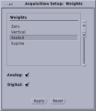
- Click on “Parameters” and select “Weights” from the drop down menu. Select the option appropriate to your experimental design (usually “seated” or “supine”) and click “Apply”.
- In order to make a template of the settings just specified, and to save time on future occasions click “Save Scan” and name the template. Subsequently this template can be selected from the top window of “Acquisition Setup” by right mouse click on “Scan” and selecting it from t the drop down menu. Your settings will then appear in the lower window.
To check these parameters are selected correctly and rule out the presence of any artefacts click “Send As Idle Parameters”. Once the parameters are configured, the selected scanner read out will be displayed on the display monitor.