Appendix E. MEG Wiring Diagram

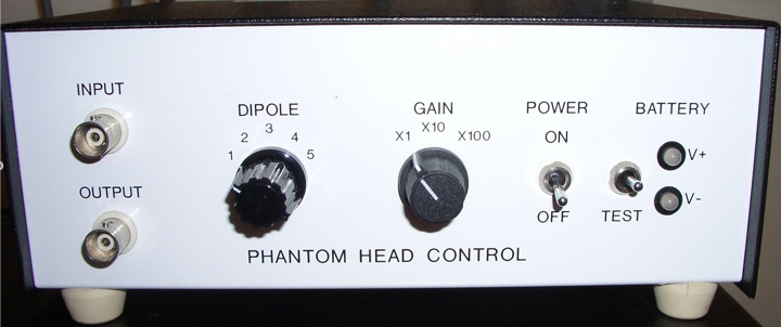
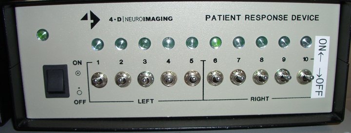
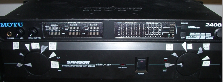
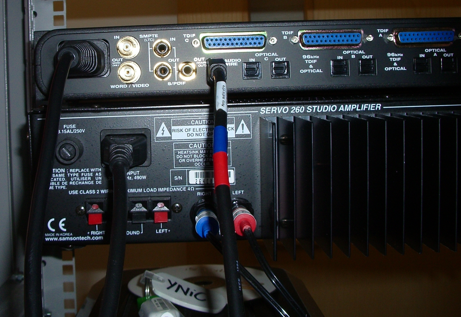
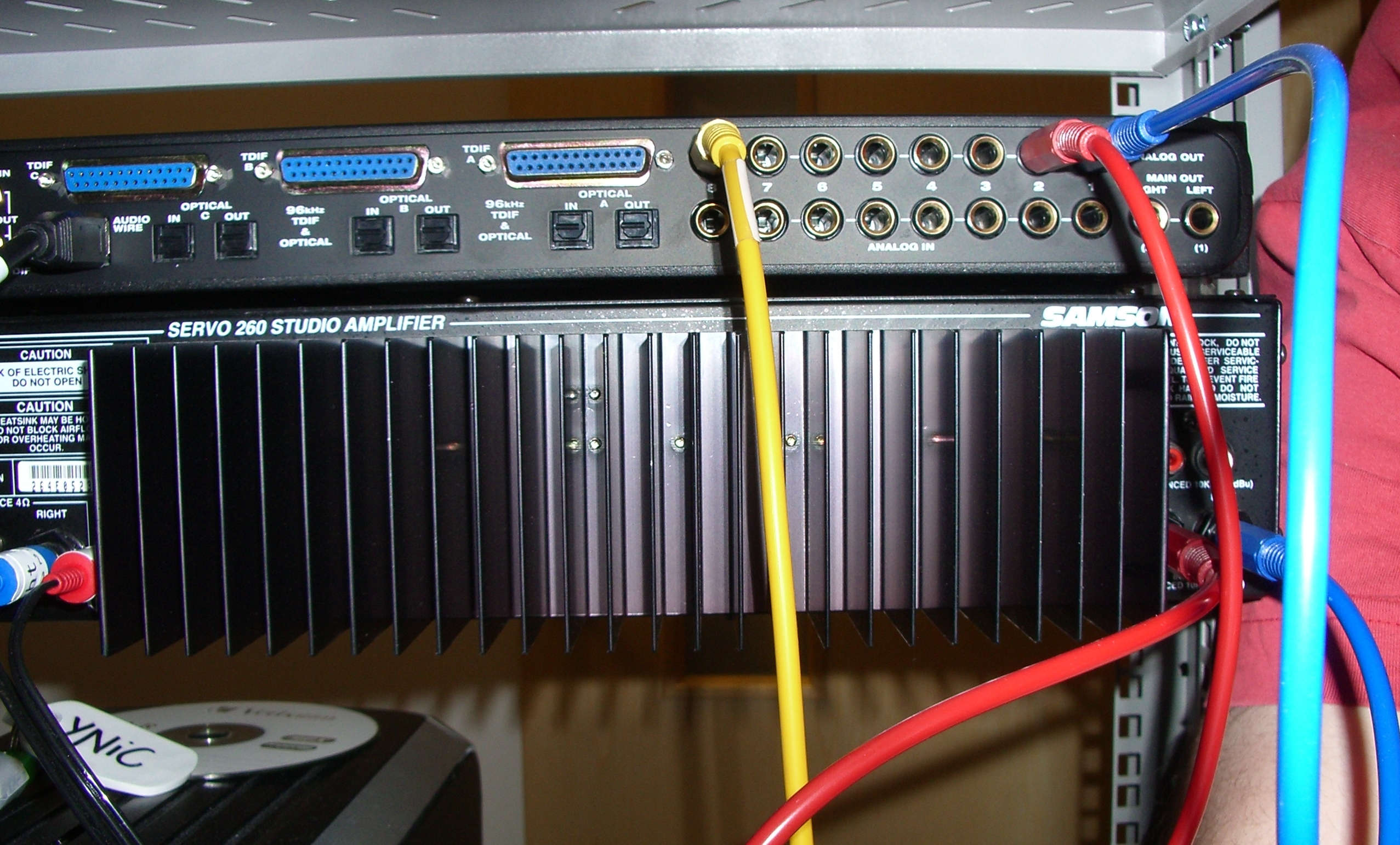
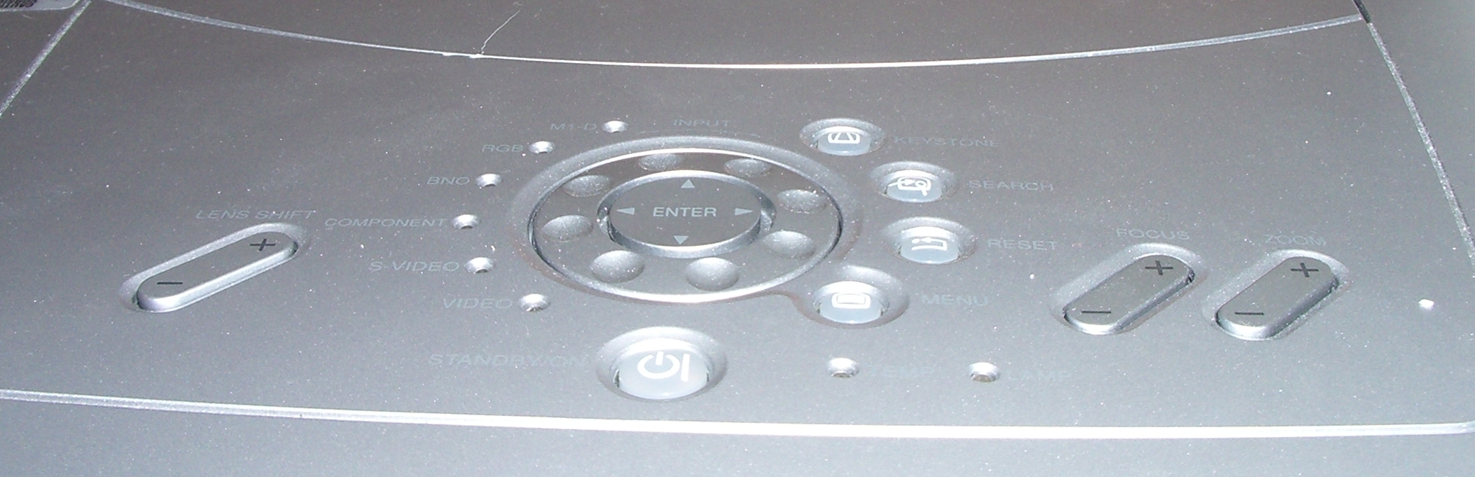
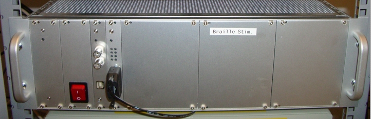
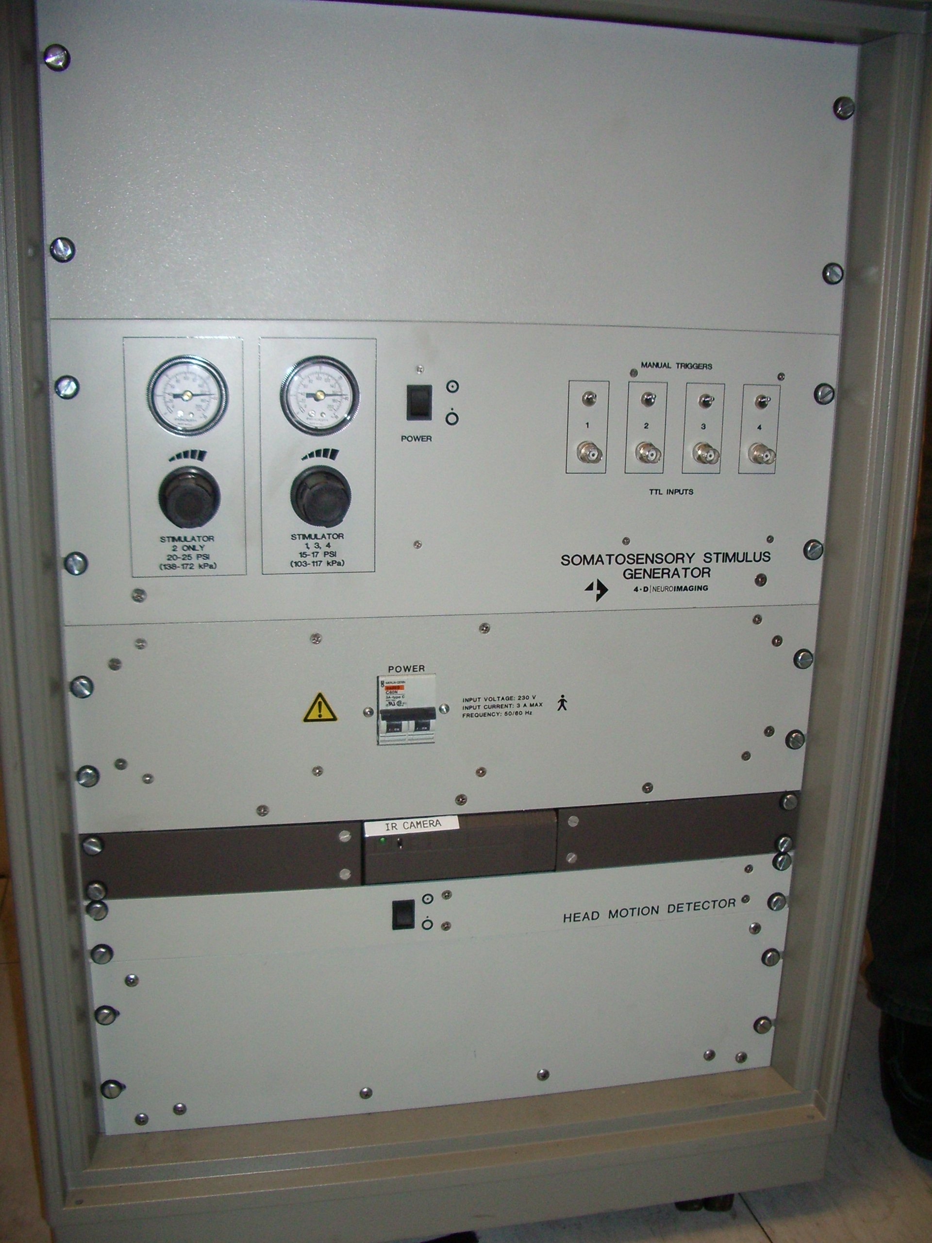
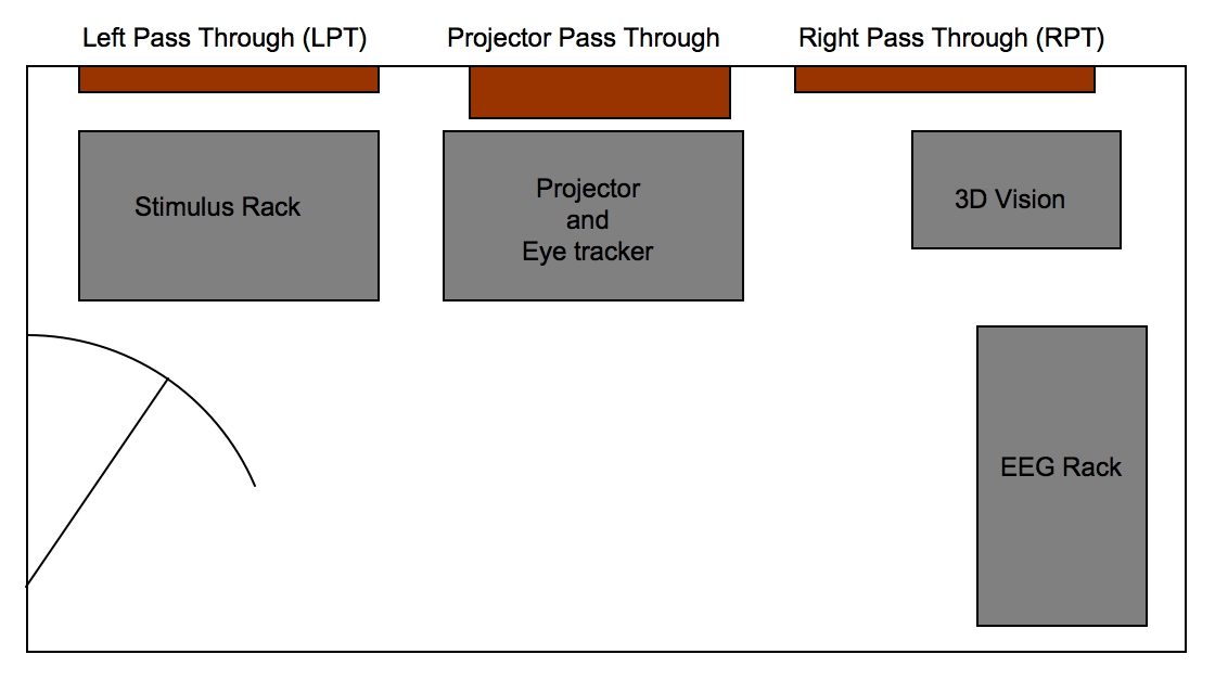
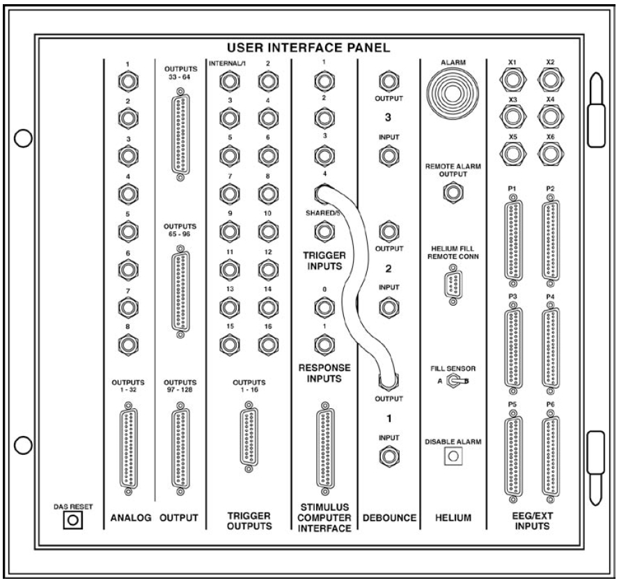
The layout of the Equipment Backroom is detailed in Figure E.1, and a wiring diagram of the Stimulus Rack is detailed in Figure E.2. There then follows a series of reference images of items of equipment from the backroom. These are here to complement the wiring diagram.

Figure E.1. MEG Equipment Backroom Diagram.

MEG Equipment Backroom Diagram.

Figure E.2. MEG Equipment Backroom Wiring Diagram.

MEG Equipment Backroom Wiring Diagram.

Figure E.3. MEG DAS User Interface Panel Schematic.

MEG DAS User Interface Panel Schematic.

Figure E.4. MEG DAS User Interface Panel.

MEG DAS User Interface Panel.

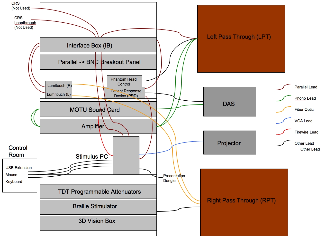
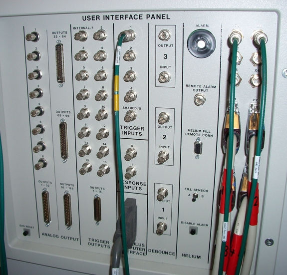
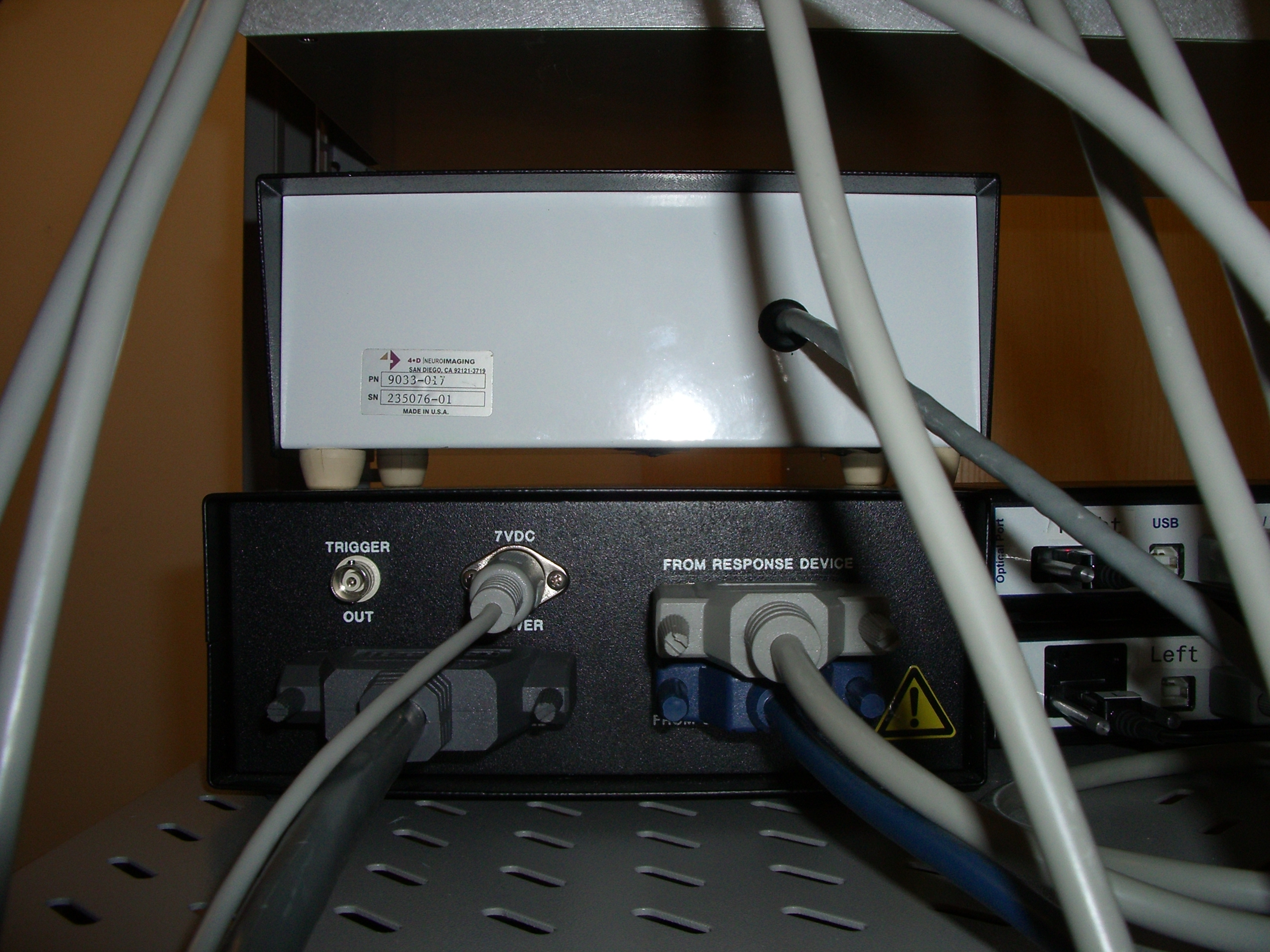
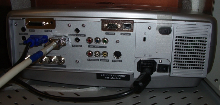
On image Figure E.4, the Green BNC connected to Trigger Input 1 (top middle), is from the MOTU sound card. The 2 green BNCs at the top right of the image are from the eye-tracker. The parallel cables at the bottom right are from the EEG. And the grey parallel cable at the bottom middle of the image is from the Interface box.

Figure E.5. MEG Stimulus Rack Interface Box (Front).

MEG Stimulus Rack Interface Box (Front).

Figure E.6. MEG Stimulus Rack Interface Box (Back).

MEG Stimulus Rack Interface Box (Back).

Figure E.7. MEG Lumitouch Control (Front).

MEG Lumitouch Control (Front).

Figure E.8. MEG Lumitouch Control (Back).

MEG Lumitouch Control (Back).

Figure E.9. MEG Phantom Head Control (Front).

MEG Phantom Head Control (Front).

Figure E.10. MEG Patient Response Device (Front).

MEG Patient Response Device (Front).

Figure E.11. MEG Phantom Head Control and Patient Response Device (Back).

MEG Phantom Head Control and Patient Response Device (Back).

Figure E.12. MEG MOTU and Amplifier (Front).

MEG MOTU and Amplifier (Front).

Figure E.13. MEG MOTU and Amplifier (Back pt1.).

MEG MOTU and Amplifier (Back pt1.).

Figure E.14. MEG MOTU and Amplifier (Back pt2.).

MEG MOTU and Amplifier (Back pt2.).

Figure E.15. MEG Visual Projector (Top): The Control Panel and Power Switch.

MEG Visual Projector (Top): The Control Panel and Power Switch.

Figure E.16. MEG Visual Projector (Top): The Control Panel and Power Switch.

MEG Visual Projector (Top): The Control Panel and Power Switch.

Figure E.17. MEG Braille Stimulator (Front).

MEG Braille Stimulator (Front).

Figure E.18. MEG Somatosensory Unit (Front): With IR Camera Swtich.

MEG Somatosensory Unit (Front): With IR Camera Swtich.